

")
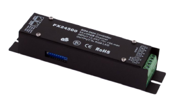
PX24500 DMX RGB Controller
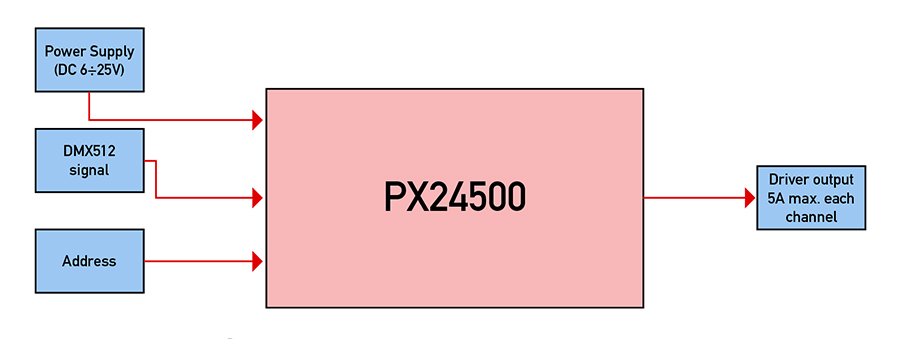
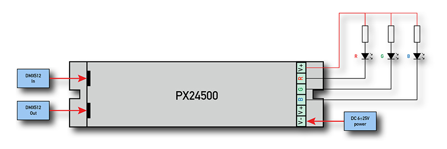
With advanced micro-computer control technology, PX series convert the widely used DMX512/1990 signal to analog constant voltage signal. It can choose 1~3 output channel, with 256-level brightness control. Useful for connecting to light console and analog device, and also for lighting & building lamps controlling.
- Meets DMX512/1990
- 256-level brightness, full-color control
- 3 output channels, can drive 5A current per channel
- With control system, can express perfect effect
- Can drive 1~3 channel of each lamp
- Can set the DMX address freely
- Anti-jamming, overload protection, overheat protection, auto-reset function.
- Customizable
- Decode Channels.: 3
- Input Signal: DMX-512/1990 digital signal
- Output Signal: 0÷24V constant voltage
- can drive 5A (each Ch.), isolated
- Power supply: DC, 12÷25V
- Power Consumption.: ≤3W
- Power Output: ≤360W (24V), ≤180W (12V)
- Operating Temp.: 0÷60°C
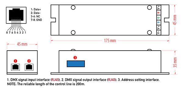
- Size: 170x45x35 mm
- Weight: 300g
- IP Grade: IP20
The DIP switch on PX24500B can set the binary value of the DMX512 address to receive data.
The correlative bits is the 1-9 bits of the DIP switch, the 1st bit is LSB,the 9th bit MSB 512 addresses totally. The start address is the first channel number of the decoder, the second channel will receive the data of start address +1, and the third channel will receive the data of start address +2. There are two way to find out the relation between the DIP switch and DMX address. Calculation method: formula: [the sum of 1~9 bit of the DIP switch] = DMX start address
- Set the n(th) bit of the DIP switch up (set to “1”) to get the value of such bit;
- Set the n(th) bit of the DIP switch down “0”, so the value of this bit is 0.
Note: the 10th bit is used for terminator.
Value of each DIP:
| DIP | 1 | 2 | 3 | 4 | 5 | 6 | 7 | 8 | 9 |
| Value | 1 | 2 | 4 | 8 | 16 | 32 | 64 | 128 | 256 |
Example 1: Set to 38Set the 6th, 3rd,1st bit of the DIP switch to “1”, others set to “0”, then the sum of the 1÷9 is 32+4+2, is the start address 38. That is: [32+4+2]=38 | 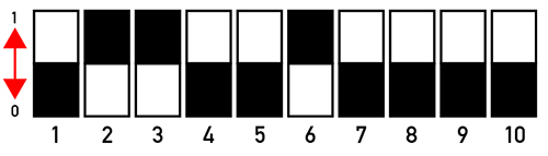 |
Example 2: Set to 226Set the 8th, 7th, 6th, 1st bit to “1”, others set to “0”, then the sum of the 1~9 is 128+64+32+2, is the start address 226. That is: [128+64+32+2]=226 | 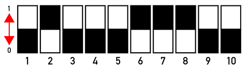 |
Principle:
- 1. The input voltage should be limited in rated range.
- 2. Do not use it by over load.
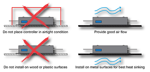
- 3. Installed in suited environment.
- A. The driver can not be setting in high temperature or wet conditions
- B. We recommend three ways to take away the heat as follows:
(a) Bared in moving air
(b) Put in a big enough space for taking away the heat
(c) Fixed on big metalline board, and make sure they are contacted well
The contents about install and usage
- 1. When work with controller, put the controller close to avoid the signal become weak.
- 2. The reliable length of the control line is 200m.
- 3. Recommend to use the STP with the characteristic impedance of 120 ohm
- 4. The signal line should be one bus, and the signal line pass in and out the decoder ports directly
- 5. Make sure the signal line connector and the decoder's signal port are well connect
- 6. Add a signal terminator at the end of the signal line
- 7. The decoder should be closed to the lamps. If the lamps is over 5 meters, the ones follow should be joined at the decoder's out port again
- 8. Adopt thicker power cable with good conductibility
- 9. If one decoder take several lamps in series , make sure the lamps's connectors are firmly connected
- 10. Signal line should be far away with the 110/220V AC cable
Install Cases:
In attached drawing, the unconscionable of install cases labeled by "X" (1)The bad install manners of take away the heat and the right ways.

Conformity with RoHS Directive 2002/95/EC - Pb. Cd. Hg. Cr+6. PbDSs 6 substances complies to RoHS standard.